Installing and commissioning a Fronius Reserva: a comprehensive guide
Author: David Conesa Albaladejo
Publication date: 27 August 2026
Last updated: 27 August 2026
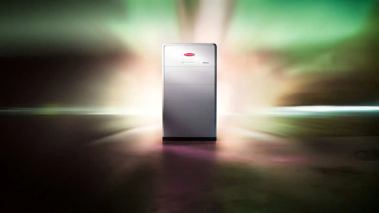
Fronius Reserva battery alongside a GEN24 Plus inverter. Image: Fronius International GmbH.
A Fronius Reserva battery is not installed on its own: it forms part of a system in which the inverter, the energy meter and —if you want a backup system— the switching components must be carefully selected and properly interconnected.
This guide sets out the requirements and steps as set out in the official Fronius documentation. This is not a substitute for the equipment manual or a qualified installer: The installation must be carried out by authorised personnel, and the necessary arrangements must be made with the supplier.
1. What you need before you start
Element
What’s it worth?
Note
Hybrid inverter
Fronius Primo GEN24 Plus, Symo GEN24 Plus or Verto Plus, including SC versions
The suffix Plus indicates battery input. A GEN24 without ‘Plus’ does not support storage
Energy meter
Smart Meter 63A-1, 63A-3, 50kA-3 · Smart Meter TS 100A-1, TS 65A-3, TS 5kA-3 · Smart Meter IP
Essential: measures consumption and mains power
Battery
Reserve 6.3 / 9.5 / 12.6 / 15.8
Compatibility depends on the inverter
Two points about meters that are often overlooked:
The Smart Meter 50kA-3 and the TS 5kA-3 They require current transformers with an output of 5 A.
The IP Smart Meter requires transformers with an output of 333 mV.
Choosing the wrong transformer is a common mistake, and it is not detected until the system is commissioned.
2. Check compatibility before buying
Primo GEN24 Plus inverters (single-phase) only support Reserve 6.3 and 9.5. They are not compatible with either the 12.6 or the 15.8, regardless of their power rating. If you need more than 9.45 kWh, you will need a three-phase inverter.
And the charging and discharging power is not determined by the battery alone: it is determined by the combination. This is the official table of nominal DC power:
Primo GEN24 Plus (single-phase)
Investor
Reserve 6.3
Rating: 9.5
12.6
15.8
Primo GEN24 3.0 Plus
3.0 kW
3.0 kW
—
—
Primo GEN24 3.6 Plus
3,6 kW
3,6 kW
—
—
Primo GEN24 4.0 Plus
4.0 kW
4.0 kW
—
—
Primo GEN24 4.6 Plus
4,5 kW
4.6 kW
—
—
Primo GEN24 5.0 Plus
4,5 kW
5.0 kW
—
—
Primo GEN24 6.0 Plus
4,5 kW
6.0 kW
—
—
Primo GEN24 8.0 Plus
4,5 kW
6.75 kW
—
—
Primo GEN24 10.0 Plus
4,5 kW
6.75 kW
—
—
Symo GEN24 Plus (three-phase)
Investor
6.3
9.5
12.6
15.8
Symo GEN24 3.0 Plus
2.56 kW
3.0 kW
3.0 kW
3.0 kW
Symo GEN24 4.0 Plus
2.56 kW
3.84 kW
4.0 kW
4.0 kW
Symo GEN24 5.0 Plus
2.56 kW
3.84 kW
5.0 kW
5.0 kW
Symo GEN24 6.0 Plus
4,5 kW
6.0 kW
6.0 kW
6.0 kW
Symo GEN24 8.0 Plus
4,5 kW
6.75 kW
8.0 kW
8.0 kW
Symo GEN24 10.0 Plus
4,5 kW
6.75 kW
9.01 kW
10.0 kW
Symo GEN24 12.0 Plus SC
4,5 kW
6.75 kW
9.01 kW
11.26 kW
Verto Plus (commercial three-phase)
Investor
6.3
9.5
12.6
15.8
Verto Plus 15.0
2.56 kW
3.0 kW
3.0 kW
3.0 kW
Verto Plus 17.5
2.56 kW
3.84 kW
4.0 kW
4.0 kW
Verto Plus 20.0
2.56 kW
3.84 kW
5.0 kW
5.0 kW
Verto Plus 25.0
4,5 kW
6.0 kW
6.0 kW
6.0 kW
Verto Plus 30.0
4,5 kW
6.75 kW
8.0 kW
8.0 kW
Verto Plus 33.3
4,5 kW
6.75 kW
9.01 kW
10.0 kW
How to read these tables. A surprising fact: with a Symo GEN24 10.0 Plus, a Reserva 6.3 only delivers 4.5 kW, whilst a 15.8 delivers 10 kW. Fitting a small battery to a large inverter limits the backup power, not just the runtime. If the aim is to power high-demand loads whilst cutting, capacity matters just as much as kWh.
These figures refer to direct current power. The alternating current power reaching the loads is slightly lower, as the inverter’s efficiency must be taken into account.
Compatibility between Fronius inverters and Reserva battery capacities. Prepared by FVComponentes based on Fronius’ technical documentation.
3. Location: where it’s allowed and where it isn’t
In this case, the manual is much more restrictive than is generally assumed.
Environmental conditions
Indoors or in a sheltered outdoor area (for example, under an eave). It is not suitable for outdoor use without protection.
IP65. It is not completely watertight and must not be submerged.
Ambient temperature: −20 to +55 °C for the Reserva, −20 to +50 °C for the PRO.
Humidity: 5 to 95 %. Maximum altitude: 2,000 m.
Avoid direct sunlight so that it heats up as little as possible.
Site requirements
Area durable and non-flammable (brick or concrete)
Effective ventilation to the outside if there is not enough space
300 mm clear space on both sides from the battery
At least 2 metres away from sources of heat (max. 60 °C) and away from flammable, explosive or chemical materials
Controls must remain accessible
It must not be covered or installed inside enclosures
Where the manual expressly prohibits its installation
This list is surprising, and constitutes grounds for the warranty to be voided:
Areas with ammonia, caustic vapours, acids or salts: stable ventilation systems, chemical plants, tanneries
Premises with farm animals (horses, cattle, sheep, pigs), stables and adjoining outbuildings
Warehouses in hay, straw, chopped fodder, concentrated feed or fertiliser
Greenhouses
Storage and processing of fruit, vegetables and wine-making products
Food preparation premises grain, green fodder and animal feed
If your project involves crop or livestock farming — which is common in self-consumption — the location must be carefully considered.
4. Space and weight
Model
Height × width × depth
Weight
Reserve 6.3
890 × 772 × 176 mm
86.5 kg
Rating: 9.5
1,140 × 772 × 176 mm
120 kg
Reserve 12.6
1,390 × 772 × 176 mm
153.5 kg
Reserve 15.8
1,640 × 772 × 176 mm
187 kg
At 176 mm deep, the tower fits into narrow corridors and rooms. But 187 kg In the large configuration, a firm floor is required: each module weighs 33.5 kg and is stacked on top of the base.
5. How to assemble the tower
Position the base plate 40–60 mm from the wall, at the same time, and levelling it by turning the adjustable feet using a 17 flat-bladed spanner.
Stack the modules side by side until they click into place on both sides with an audible click. That click confirms that the module has made contact correctly.
Place the battery management system (BMS) on top of the last module, also until you hear the click.
Safety during assembly
At least two people for lifting and positioning
Use the built-in carrying handles
PPE: insulating gloves, safety goggles and protective clothing
Remove watches, bracelets and rings: There are high-voltage connections
Clean terminals: a lint-free cloth and without cleaning products
Regarding earthing: The modules are already connected to one another via a common earth connection, which ensures equipotentiality. An additional earth connection is neither required nor permitted on individual modules. The protective conductor is secured using the M4x10 TX20 screw supplied, to 3 Nm of torque.
6. Communications: the cabling that determines whether it works
The backup system does not simply connect to the mains; it needs to communicate with the inverter.
Inverter ↔ Smart Meter: CAT5 or higher, Modbus RTU (RS485)
Inverter ↔ IP Smart Meter: Modbus RTU or Modbus TCP via WLAN or LAN
Cable specifications
Connection
Specification
Data communication
RJ45, minimum CAT 5 STP shielded. Maximum 30 m
Inverter ↔ battery cable
Maximum 40 m
DC cables
They must comply EN 50618 or IEC 62930
DC terminals (PRO Reserve)
Stäubli MC4 EVO STO, 6 or 10 mm², stripped to 7 mm
Protective conductor
Tinned copper 2.5–6 mm², 4 mm drill bit, 3 Nm
Cables that do not comply with EN 50618 or IEC 62930 have a lower current-carrying capacity, and it is the installer’s responsibility to ensure they are correctly sized.
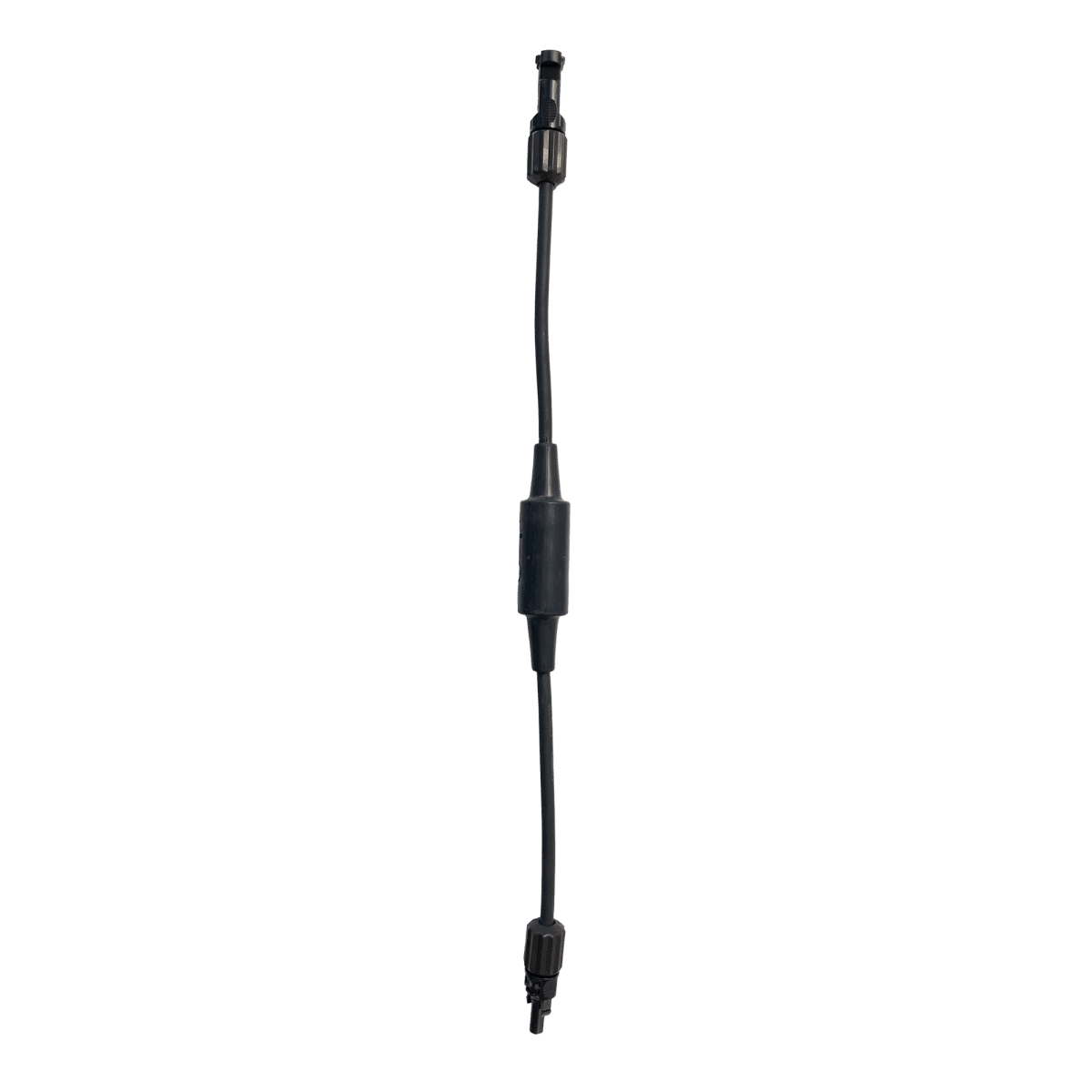
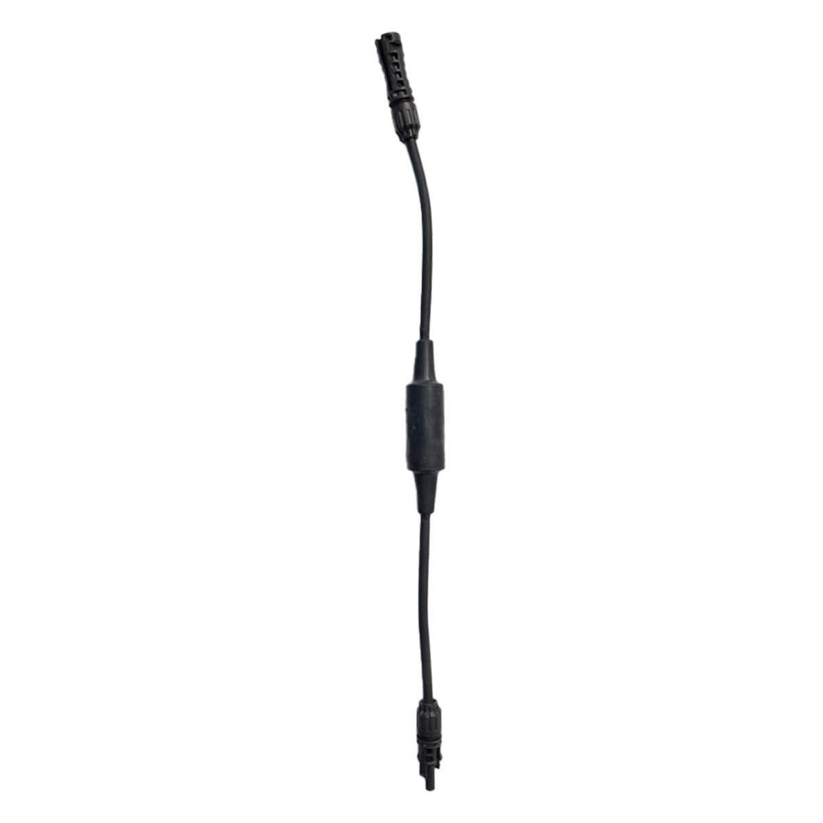
In-line fuse with connector Amphenol, for GEN24 PlusIn-line fuse with connector Stäubli MC4 Evo Stor, for Verto Plus and Reserva PRO
The two DC connection systems are not interchangeable. Images: Fronius International GmbH.
Four factors that cause commissioning to fail
Termination resistors. They are configured using microswitch (DIP) in the battery and come enabled by default (ON). You need to check them depending on whether the system has a single battery or several in parallel. This is the number one cause of intermittent communications.
Updated firmware in the inverter and battery. With outdated versions, the battery may not be recognised.
The DC connection depends on the inverter. Amphenol is used with GEN24 Plus; with Verto Plus, MC4 EVO STOR.
The The smart meter connects to the 10-pin connector, pins M0+, M0− and GND.
What do the battery LEDs tell you?
Indications
Meaning
Charging LEDs are lit
SoC level: < 25 %, < 50 %, < 75 %, < 100 %
Flashes once per second
Battery loading
It flashes twice a second
Getting started o connecting to the inverter
Permanent power supply
Stable, achieved state
7. Choose the backup option
You need to make a decision before buying equipment, because Only one variant can be implemented. They do not go together.
Comparison of the three backup options. Produced by FVComponentes based on Fronius’ technical documentation.
PV Point (built-in)
A powered socket during the power cut
Single-phase, up to 3 kW. Battery optional
Requires 30 mA Type A residual current device
No additional components are required: it comes as standard with the inverter
One shot continuously fed, as a backup and in parallel with the grid
Single-phase, up to 3 kW. Optional battery
Requires 30 mA Type A residual current device y 13 A circuit breaker
Full Backup
Feed the whole house, single-phase and three-phase
Manual or automatic switching
Requires a battery — it is not optional
Requires additional contactors or auxiliary relays
The requirements vary depending on the country and the distributor
Two important restrictions:
PV Point and PV Point Comfort are not available on the Verto Plus. With Verto, the only option is Full Backup.
Full Backup is not available on the Symo GEN24 3.0, 4.0 and 5.0 Plus.
For a Full Backup, the Backup Controller and the Fronius Backup Switch They allow for automatic or manual switching and are installed directly in the switchboard, without the need for an external switch box.
8. How failover works
The purpose of switching is disconnect the property from the mains before operating in island mode. This is not just a regulatory whim: it prevents power from being supplied to a circuit that maintenance staff may be working on.
In normal operation, the disconnect contactors are closed and the house is connected to the grid.
When the power cut occurred, the power supply to the coils is automatically cut off. The contactors open, completely disconnecting the system from the mains supply. The feedback contacts change state; the inverter detects this and activates the backup relay, which keeps the contactors open. Thus, if the grid is suddenly restored, the system does not couple in parallel in an uncontrolled manner.
On the Symo GEN24 Plus, the switching time is less than 90 seconds, up to a maximum of 3,680 W per phase and a peak of up to 12,100 VA.
The control wiring is carried out using shielded cable 8-pole CAT5-7 (8 × 0.5 mm²), on the 16-pin connector of the investor.
9. Step-by-step set-up
Firstly: apply tension in the correct order
Set the battery DC isolator set to «On»
Close the disconnector cover until you hear the click and secure it with the screws
Connect the circuit breaker and put the DC disconnector on the inverter set to «On»
Option A — using the Fronius Solar.start app
Download and install Fronius Solar.start
Open the inverter’s access panel by touching the sensor. The communication LED is flashing blue
Open the app and Scan the QR code on the inverter’s rating plate
Add the battery via the inverter interface
Option B — via a web browser using Wi-Fi
Open the access point by touching the sensor
Connect to the network FRONIUS_ + serial number. The password is on the inverter’s rating plate
Open in browser 192.168.250.181
Insert the battery
If you’re using Windows 10: To enter the password, you must first click the link «Connect using a network security key instead». Otherwise, you won’t be able to type it in.
Option C — via Ethernet cable
Connect the inverter via LAN1 with CAT5 STP cable or higher
Open the access point by touching the sensor
Open in browser 169.254.0.180
Access to the device settings
Menu settings Equipment configuration Only trained staff can carry them out: they require log in as the «Technician» user».
Update the firmware
Access the inverter interface and log in
Go to System > Update
Drag the firmware file into the field shown
Updates can be found on the product page and in the Download Search section on fronius.com.
10. Maintenance, and the 7-day period that can ruin the battery
The battery is maintenance-free. Repairs are carried out only by specialist technical staff.
Cleanliness: A damp cloth if necessary. Never use cleaning products, abrasives or solvents.
And now for the most important piece of information in the manual, which almost nobody knows:
If the battery falls below its minimum charge level, it must be recharged within 7 days. Once this period has elapsed, the modules may suffer irreparable damage due to a complete discharge.
The forced reload Charging takes place automatically using solar or mains power when the minimum SoC is reached, provided that two conditions are met: the The DC isolator is in the «On» position» and the The inverter is connected to the mains.
This has a serious practical implication: if you leave the system switched off whilst you are away for a long period —a second home that is closed off in winter, a building site that has come to a standstill— and if the battery falls below the minimum level whilst the isolator is open, it cannot protect itself. Status messages appear on the inverter’s interface, and on Fronius Solar.web allows you to set up email alerts. Turn them on.
Dark start
If the battery has switched off due to deep-discharge protection, it will not start on its own: you need to black screen on start-up by manually setting the DC isolator to «On». The same applies when starting emergency power mode following a power cut: the inverter requires power from the battery and this must be supplied manually.
Before working on the battery: All status LEDs must be completely switched off, and you have to wait for the inverter’s capacitors to discharge.
11. Monitoring and optimisation
The entire system is monitored from Fronius Solar.web: solar generation, battery charging and discharging, and household consumption.
And there’s a feature that helps you get the most out of your battery if you’re on an index-linked tariff: the Fronius Energy Cost Assistant. Use AI to analyse your electricity generation, consumption and prices in order to charge the battery from the mains when the electricity tariff is low and use it when it goes up.
12. Expand the system at a later date
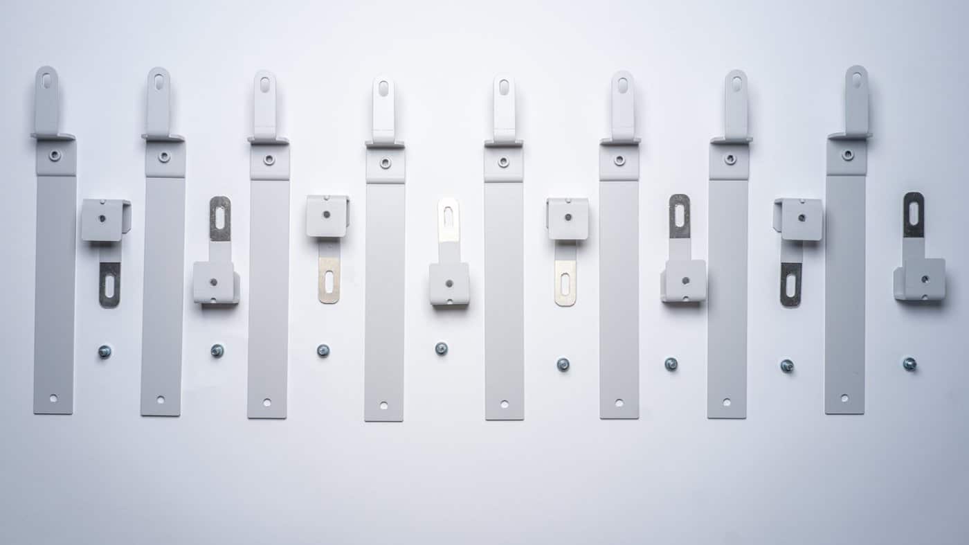
Set-up of two towers in parallel using the mounting kit. Image: Fronius International GmbH.
The Reserve is modular, comprising two levels: 2 to 5 modules inside the tower, preserving the BMS and the base, and up to 4 batteries in parallel.
However, the expansion has the same limitation as the initial installation: The Primo GEN24 Plus does not support versions higher than Reserva 9.5. If you’re planning to grow, that decision needs to be made when choosing an investor, not afterwards.
Frequently asked questions
Can I install a Reserva 15.8 with a Primo GEN24 Plus?
No. Fronius limits the Primo GEN24 Plus to the 6.3 and 9.5 configurations. For 12.6 or 15.8, you’ll need a Symo GEN24 Plus or a Verto Plus.
Do I absolutely have to have a smart meter?
Yes. The meter provides the inverter with information on the property’s energy consumption and grid energy. Without it, surplus energy management and battery charging do not work properly.
Can I run PV Point and Full Backup at the same time?
No. Only one backup variant can be implemented per installation.
Does the battery work without a backup configured?
Yes. It stores energy and increases your self-consumption as normal. What it won’t do is power the house during a power cut.
What happens if I leave the house locked up for several months?
This is the risk scenario. If the battery voltage falls below the minimum level and the isolator switch is open or the inverter is switched off, forced recharging cannot be carried out. If the modules remain below the minimum temperature for more than 7 days, they may suffer irreparable damage. Change your operating system and enable email notifications on Solar.web.
How long does it take to switch over when the power goes out?
With the Symo GEN24 Plus, it takes less than 90 seconds to start up in stand-alone mode.
What is the maximum cable length between the inverter and the battery?
40 metres. And the communication cable: 30 metres at most, minimum CAT 5 shielded.
Can anyone install it?
No. The installation must be carried out by an authorised installer, and the switchover to backup power must be agreed with the electricity supplier.
Do you have any queries about your project?
At FVComponents we are Fronius System Partner and Official Service Partner in Spain. If you’re sizing a system with a backup and want to check the inverter–battery–meter combination before buying, please get in touch and we’ll go through it with you.
Recommended settings for configuring the Victron and SmartShunt on the VictronConnect with lithium and lead-acid batteries: discharge limit 5%, Peukert 1.05, tail current 4% and above, with a step-by-step video guide.
The Pylontech US are batteries for domestic use. We’ll explain which certifications a vehicle requires (R10, SAE J1455), how vibration affects them, what the warranty covers, and what happens with insurance in the event of a fire.
Do you have an Android tablet or mobile phone gathering dust in a drawer? With the Victron Energy Android GX WiFi Display app, you can turn it into a fixed wireless display for your Cerbo GX, Ekrano GX or any device with GX built-in. Victron has just released version 1.2, which makes the connection more stable, so
A step-by-step guide to powering CCTV cameras using solar energy on farms, construction sites or industrial premises without mains electricity: power consumption, batteries, solar panels, 4G and common pitfalls to avoid.
We use our own and third-party cookies to obtain statistical data on our users' browsing habits, offer personalised marketing and improve our services.
Functional
Always active
The storage or technical access is strictly necessary for the legitimate purpose of enabling the use of a specific service explicitly requested by the subscriber or user, or for the sole purpose of carrying out the transmission of a communication over an electronic communications network.
Preferences
The technical storage or access is necessary for the legitimate purpose of storing unsolicited preferences of the subscriber or user.
Statistics
Technical storage or access that is used exclusively for statistical purposes.Technical storage or access that is used exclusively for anonymous statistical purposes. Without a request, voluntary compliance by your Internet Service Provider, or additional records from a third party, information stored or retrieved solely for this purpose cannot be used to identify you.
Marketing
Technical storage or access is necessary to create user profiles to send advertising, or to track the user across a website or across multiple websites for similar marketing purposes.