- Free shipping to mainland Spain for orders over 300€.
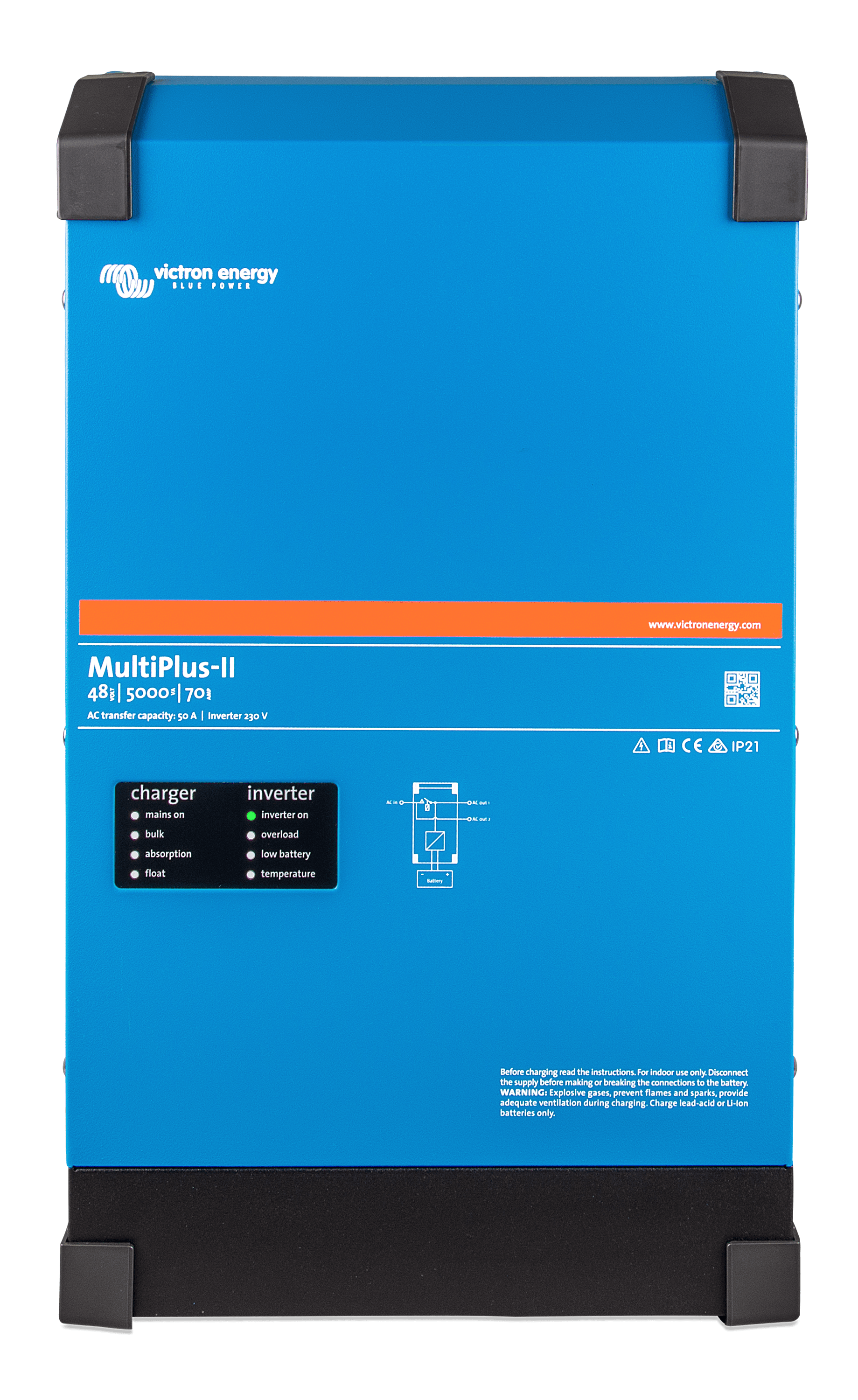
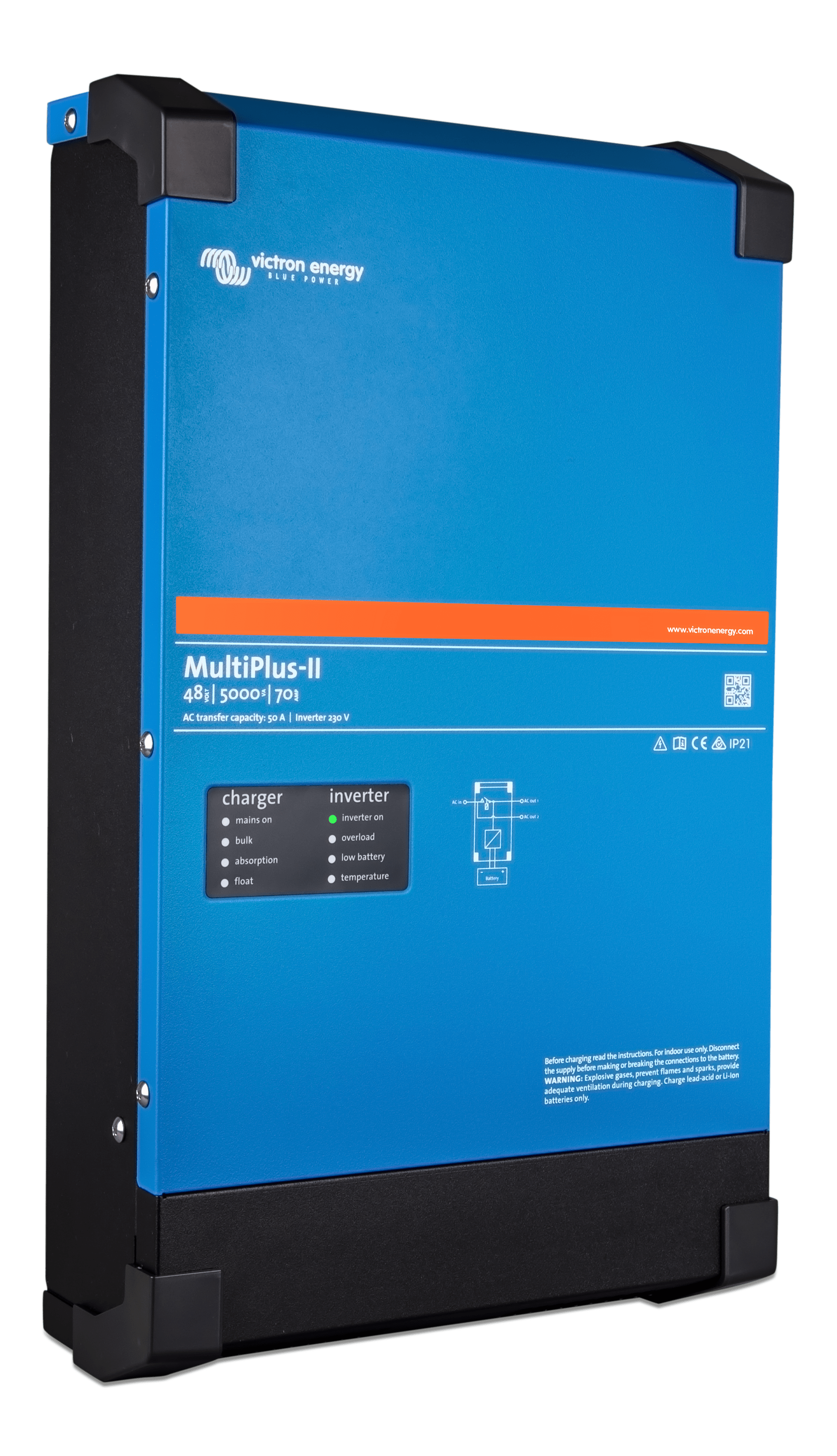
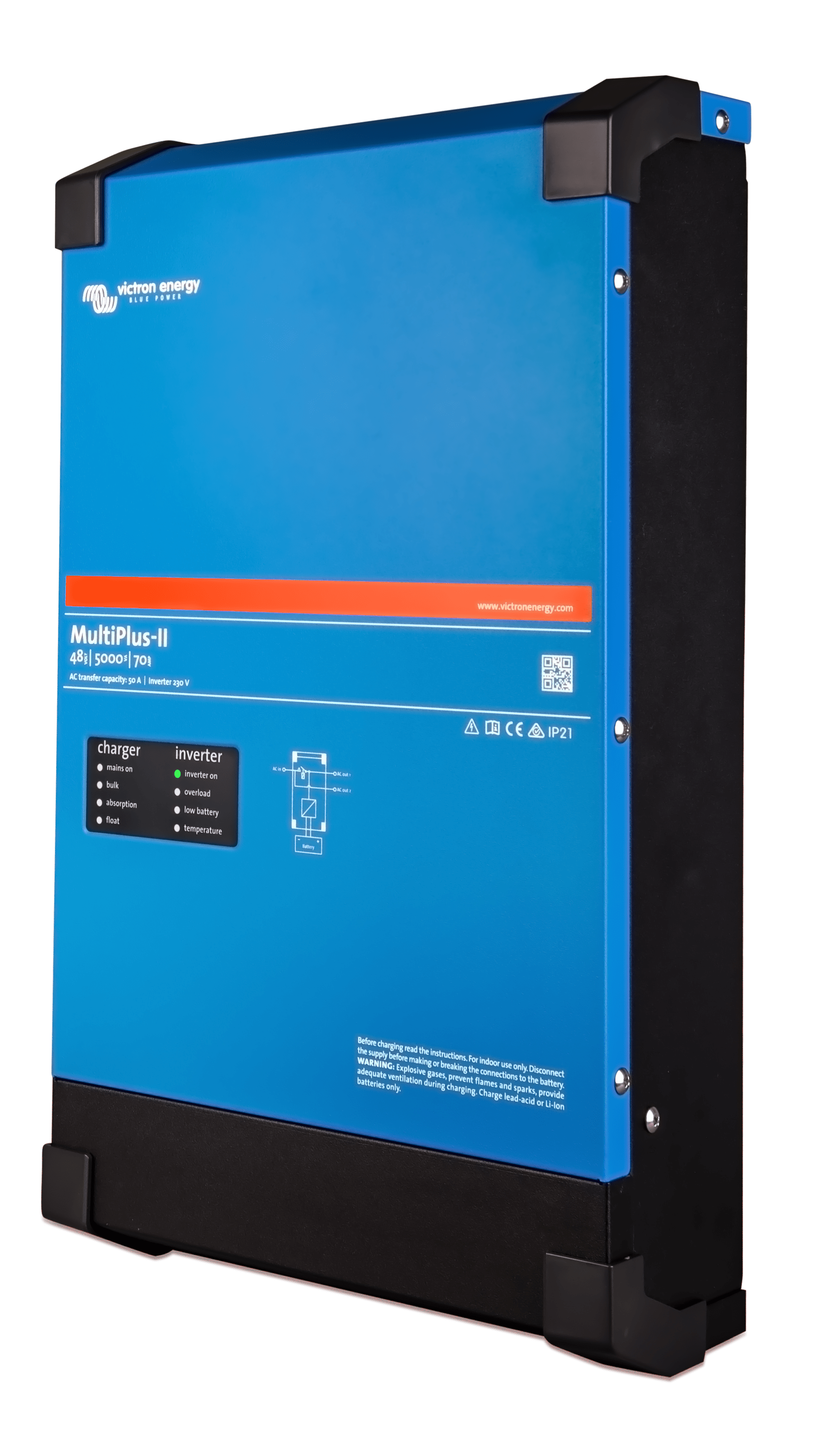
Inverter Charger 48V Victron MultiPlus II 48/5000 VA 48V 70+50A - PMP482505010
847,86€
TAXES INC.
- 48V inverter charger
- Power Inverter: 5000 W
- Peak Power: 9000 W
- Integrated charger: 70A
- AC Outputs: 2
- Compatible with the GX range
Producto disponible para la venta

Finance your purchase with Cetelem
Reference:
PMP482505010
Categories: Investors, Inverter Chargers 48V to 220V, Top sales
Product information
Inverter Charger 48V Victron MultiPlus II 48/5000 VA 48V 70+50A - PMP482505010
The Inverter Charger 48V Victron MultiPlus II 48/5000 VA 48V 70+50A - PMP482505010 is an inverter charger that combines the functions of the MultiPlus and MultiGrid inverter models. The Victron Multiplus II is perfect for marine, recreational boating, vehicle and off-grid land applications. In addition, it has built-in anti-islanding functionality.
Inverter Charger 48V Victron MultiPlus II 48/5000 Inverter Charger Specifications
Technical data of the inverter
- DC input voltage range: 38V - 66 V
- Output voltage: 230 V AC ± 2 %
- Frequency: 50 Hz ± 0,1 %
- Power cont. output at 25 ºC: 5000 VA
- Power cont. output at 25ºC: 4000 W
- Power cont. output at 40 ºC: 3700 W
- Power cont. output at 65 ºC: 3000 W
- Maximum apparent net balance (current returned to the grid): 5000 VA
- Peak power: 9000 W
- Maximum efficiency: 96%
- No-load consumption: 18 W
- No load consumption in AES mode: 12 W
- Idle consumption in search mode: 2 W
Technical data of the charger
- Input voltage range: 187-265 V AC
- Input frequency: 45 - 65 Hz
- Absorption" charging voltage: 57,6 V
- Float" loading voltage: 55,2 V
- Storage mode: 52,8 V
- Maximum battery charging current: 120 / 70 A
- Battery temperature sensor: Yes
General data Victron Multiplus 2
- Transfer switch: 50 A
- Maximum AC input current: 50 A
- Auxiliary output: 32 A
- External AC sensor (optional): 50 A
- Programmable relay: Yes
- Protection: IP22
- Battery connection: M8 bolts
- 230 V AC connection: Screw terminals 13 mm² (6 AWG)
- Weight: 19kg
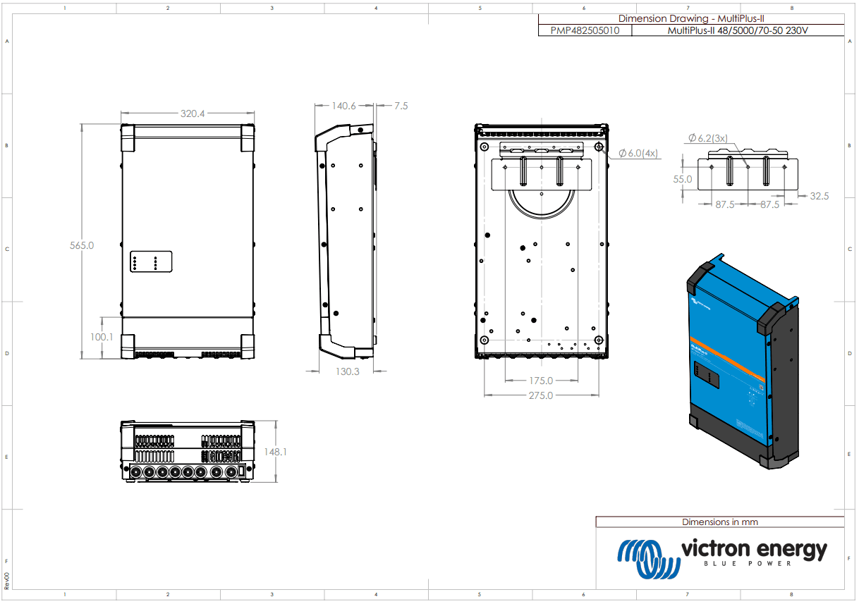
- Dimensions: 565 x 320 x 149 mm
Features of the MultiPlus II 48/5000 VA
PowerControl: The Victron inverter charger will take into account the other AC loads and use the excess current to charge the battery, thus avoiding overloading the generator or the grid.
PowerAssist: This function of the Multiplus 48/5000 allows more output power to be supplied by adding power from the AC input and also from the batteries so as not to overload the external mains input. This is used when peak power is required for a short period of time.
Various configurations of the Victron Multiplus-ii 5000va/48v/70a: The MultiPlus II can be used in grid-connected and off-grid photovoltaic systems. It is compatible with solar charge controllers and grid-connected inverters.
Two AC outputs: The MultiPlus 2 takes over the connected loads in the event of a power failure or disconnection of the port/generator socket. The second output is activated when the input of the Victron 48/5000 has AC power; for connecting devices that should not discharge the battery, e.g. a water heater.
Programmable relay: It can be programmed for different applications, e.g. as a starting relay for a generator.
Parallel connection is possible:
- Up to 6 Multiplus can be connected in parallel. 6 units of Victron Multiplus-ii 48v 5000va 48v 70+50a Inverter will give an output power of 25 kW/30 kVA and a load capacity of 420 amps.
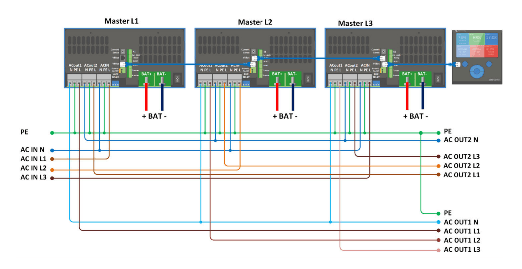
- It is also possible to configure 3 units of the same model for a three-phase output.
- In addition, up to 6 sets of 3 units can be connected in parallel.
Installation and assembly of the Victron MultiPlus II 48/5000 VA Inverter - PMP482505010
Dimensions of the Victron Multiplus II 48/5000:
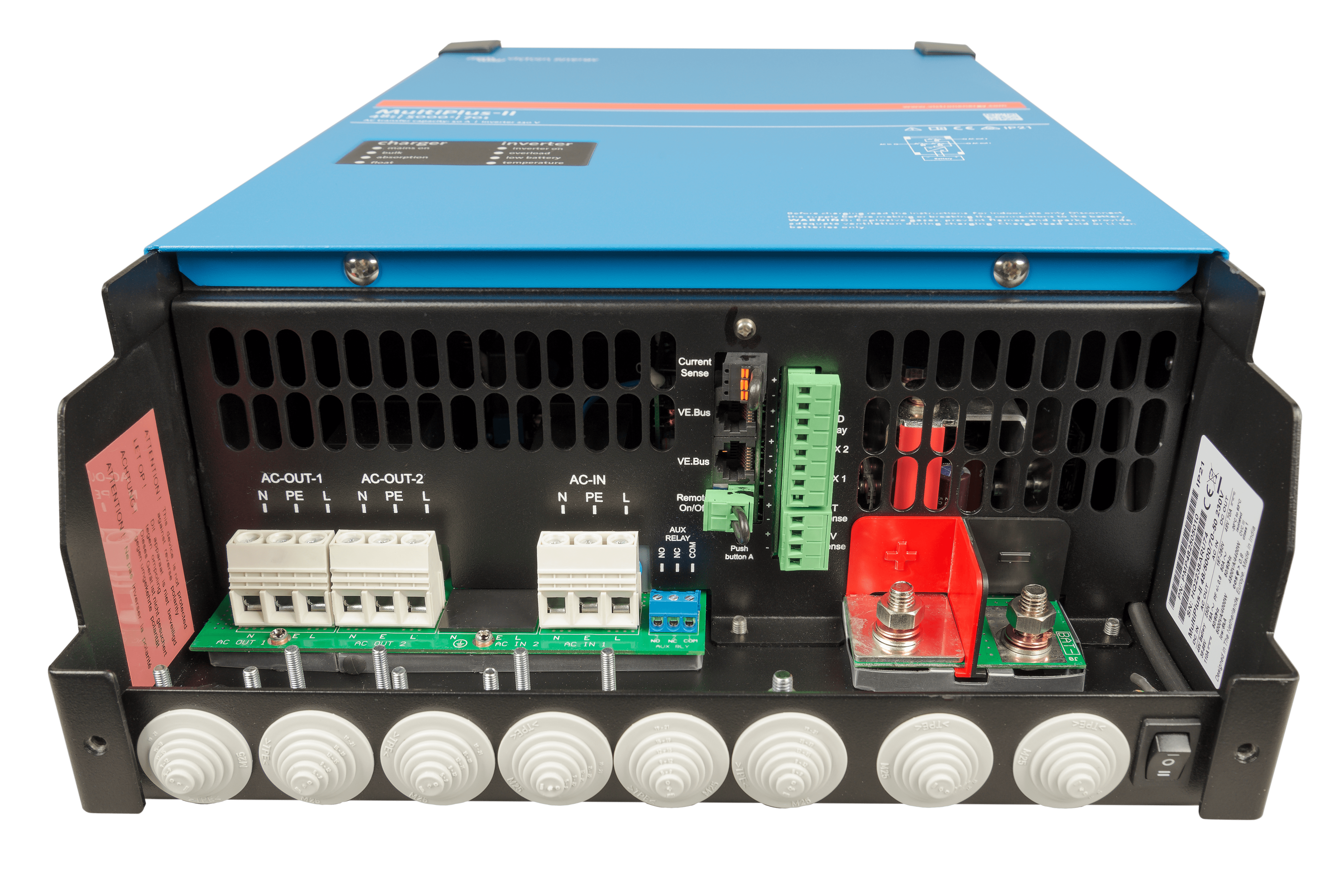
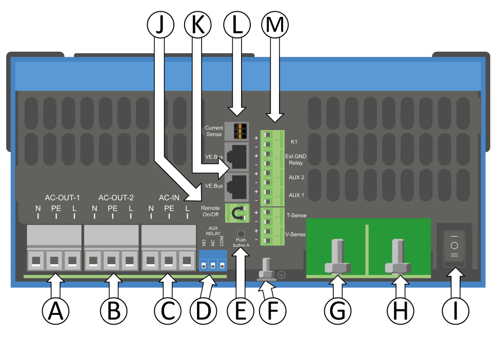
Victron 5000w Inverter Connections
- A - Load connection. AC-out-1. From left to right: N (neutral), PE (earth), L (phase).
- B - Load connection. AC-out-2. From left to right: N (neutral), PE (earth), L (phase).
- C - AC input: From left to right: N (neutral), PE (ground), L (phase)
- D - Alarm contact: (from left to right) NO, NC, COM.
- E - Press button A - To perform a start without assistants.
- F - Primary earth connection M6 (PE).
- G - Positive battery connection M8.
- H - Negative battery connection M8.
- I - switch: 1=On, 0=Off, ||=charger only
- J - Remote switch connector: Jumper to activate.
- K - 2 RJ45 VE.Bus connectors for remote panel and/or parallel or three-phase operation
- L - External current sensor
- To connect the current sensor, remove the jumper between the INT and COM terminals, connect the red sensor wire to the EXT terminal and connect the white sensor wire to the COM terminal.
- M -Terminal for (top to bottom):
- 1. 12 V 100 mA
- 2. Programmable contact K1 open collector 70 V 100 mA
- 3. External earthing relay +
- 4. External earthing relay -
- 5. Aux. input 1 +
- 6. Aux. input 1 -
- 7. Aux. input 2 +
- 8. Aux. input 2 -
- 9. Temperature sensor +
- 10. Temperature sensor -
- 11. Battery voltage sensor +
- 12. Battery voltage sensor -
Location of the installation
- The Victron Multiplus-ii 48v 5000va 48v 70+50a inverter should be installed in a dry and well ventilated area.
- A 10cm space should be left around it for ventilation.
- Can be installed on the wall, with a built-in mounting accessory.
- The distance between the product and the battery should be as short as possible to minimise voltage loss in the cables.
- The presence of chemicals, synthetic components, curtains or other textiles, etc. should be avoided.
Connecting the battery to Victron 48/5000
- The battery should be 200 - 800 Ah and the fuse should be 200A.
- For 0-5 m long cables, the cable cross-section should be 70 mm2.
- For cable lengths of 5-10 m, the cable cross-section should be 120 mm2.
AC wiring connection
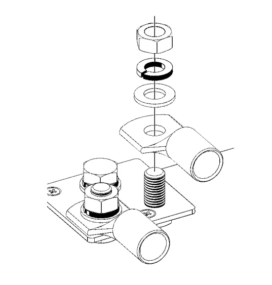
- The recommended torque for M8 bolts such as those of the Multiplus 48/5000 Inverter is 12 Nm.
- Do not reverse neutral and phase when connecting AC power.
- AC-In
- The AC input cable can be connected to the "AC-In" terminal block.
- From left to right: "N" (neutral), "PE" (earth) and "L" (phase).
- The AC input must be protected by a 50 A fuse.
- If the AC input power supply has a lower nominal value, the fuse or magnetic circuit breaker must also be reduced accordingly.
- AC-out-1
- The AC output cable can be connected directly to the AC-out terminal block.
- From left to right: "N" (neutral), "PE" (earth) and "L" (phase).
- An earth leakage circuit breaker and a fuse or circuit breaker capable of withstanding the expected load, in series with the output, and with a suitable cable cross-section, must be included.
- AC-out-2
- There is a second output that disconnects its load in case of battery operation. On these terminals, equipment is connected that can only be operated if AC voltage is available at AC-in-1, e.g. an electric boiler or an air conditioner. The load of AC-out-2 is disconnected immediately when the inverter/charger switches to battery operation. Once the AC-in-1 inputs have AC power, the load on AC-out-2 will be reconnected with a delay of approximately 2 minutes. This allows the generator to stabilise.
- AC-In
For more detailed information on how to set up an ESS installation, please consult the Victron manual ESS design and installation.
If you want to make a Camper installation, see our blog post "Schematic Victron Multiplus for Camper Van PDF"where you will find the Victron schematic diagram of the Multiplus installation.
Victron Multiplus-ii 5000va/48v/70a Charging Algorithm
4-stage charging:
- Initial load
- It starts when the charger is started. A constant current is applied until the nominal battery voltage is reached, depending on temperature and input voltage, after which a constant current is applied until the point at which excessive gassing begins (resp. 14.4 V, 28.8 V or 57.6 V with temperature compensation).
- BatterySafe
- The voltage applied to the battery gradually increases until the set absorption voltage is reached. The BatterySafe mode is part of the calculated absorption time.
- Absorption
- The absorption period depends on the initial charging period. The maximum absorption time is the maximum absorption time set.
- Flotation
- The float voltage is applied to keep the battery fully charged.
- Storage
- After one day of float charging, the output voltage is reduced to storage level. This is 13.2 V for 12 V batteries, 26.4 V for 24 V and 52.8 V for 48 V batteries. This will keep water loss to a minimum when the battery is stored during the winter season. After a period of time that can be set (default = 7 days), the charger will enter "Repeated Absorption" mode for a period of time that can be set (default = 1 hour) to "refresh" the battery.
Configuring the Victron Multiplus
The Victron Multiplus 48/5000 is delivered with the standard factory settings, which are the values suitable for the operation of a single Multiplus.
Some settings and their significance:
- Inverter frequency
- Output frequency if there is no AC at the input.
- Setting: 50 Hz, 60 Hz
- Input frequency range
- Input frequency range accepted by the Victron Multiplus ii. The inverter charger is synchronised within this range to the input AC frequency. The output frequency is then equal to the input frequency.
- Setting: 50, 60 or 45 - 65 Hz.
- Input voltage range
- Voltage range accepted by the Victron Multiplus ii 48/5000. The inverter charger is synchronised within this range with the input AC. The output voltage is then equal to the input voltage.
- Adjustments:
- Lower limit: 180 - 230 V
- Upper limit: 230 - 270 V
- Adjustments:
- Voltage range accepted by the Victron Multiplus ii 48/5000. The inverter charger is synchronised within this range with the input AC. The output voltage is then equal to the input voltage.
- Inverter voltage
- Output voltage of the Victron Multiplus ii 48/5000 running on battery.
- Setting: 210 - 245 V
- AES (automatic economy switch)
- If this parameter is activated, the power consumption in no-load and low-load operation decreases by approximately 20 %, slightly "narrowing" the sinusoidal voltage.
- Battery charging algorithm
- The standard value is "Variable four-phase with BatterySafe mode". This is the recommended charging algorithm for lead-acid batteries.
- Initial charge protection
- When this parameter is "On", the initial charging time is limited to 10 hours. A longer charging time could indicate a system error.
- AC input current limit
- Current limiting settings with which PowerControl and PowerAssist are operated.
- Topology in line with the network: 6-50A.
- Grid-parallel topology with external 50 A or 100 A current transformer: 6 - 50/100.
- Weak AC
- The charger will also accept a highly distorted voltage at the cost of increased distortion of the input current.
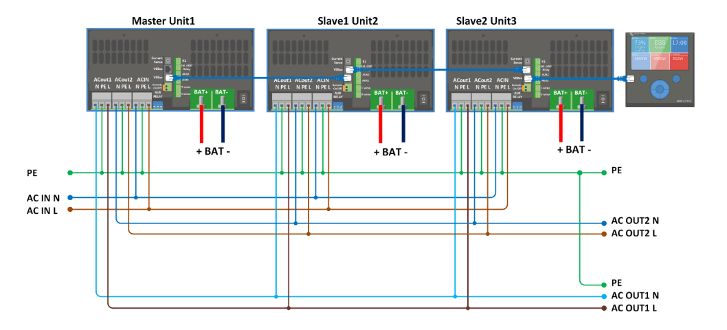
Parallel configuration of the Victron Inverter Charger PMP482505010
- Only up to 6 units of the same model (identical devices) are allowed in parallel.
- All units must be connected to the same battery.
- The DC connection cables for the devices must have the same length and cross-section.
- If a negative and a positive DC distribution point are used, the cross-section of the connection cables between the batteries and the DC distribution point must be at least equal to the sum of the cross-sections required for the connections between the distribution point and the inverters/chargers.
- Place the inverter/chargers close to each other but leave at least 10cm around each inverter for ventilation.
- UTP cables must be connected directly from one unit to the other (and to the remote panel). No junction or distribution boxes are allowed.
- Always interconnect the negative battery cables before laying the UTP cables.
- Only one remote control medium (panel or switch) can be connected to the system.
Three-phase configuration of the Multiplus II 48/5000
The devices are connected with standard RJ45 UTP cables (same as for parallel operation).
Victron Multiplus ii 48/5000 applications
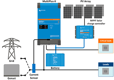
MultiPlus II inverter used as UPS (Uninterruptible Power Supply).
The Victron Multiplus 2 inverter charger can power the usual loads and have an energy storage system (battery) that will power critical loads if the grid fails or is unstable. This way we can have our own UPS to power vital equipment that requires a secure power supply, such as data centres, telephone or internet repeaters, hospitals, emergency centres... The possibilities are almost unlimited, as we can reach a size of almost 300kVA of power in three-phase.
MultiPlus II inverter used as a 48V hybrid inverter, connected to the grid to dump surpluses and with solar panels via MPPT regulator.
The Multiplus 48/5000 inverter will optimise self-consumption by supplying energy to its output from the solar panels connected to a Victron MPPT regulator and in turn to a battery bank. The energy generated by the solar panels will go to the loads connected to the inverter, the surplus will be stored in batteries and when the battery is full, the solar surplus will be fed to the grid to take advantage of the surplus compensation.
At night, the energy stored in the batteries is used first, and when the batteries reach a minimum level, the grid is used to power the loads connected to the inverter.
In the event of a power failure, the Victron Multiplus-ii 5000va/48v/70a0 will behave as an uninterruptible power supply (UPS) supplying power to the loads without interruption by a mains power failure. It is ideal for areas where there are regular power outages or where the grid is unstable or with many power surges or dips.
Victron Multiplus II 48V 5000VA 70+50A Inverter Battery Compatibility
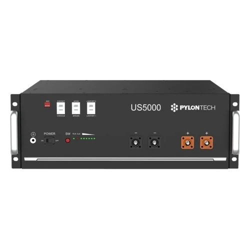
The MultiPlus II can work with virtually any 48V battery on the market, both lithium and lead acid, without any problem. Its great flexibility and adaptability allows it to be configured to charge a lead-acid battery of any technology, whether sealed or open OPzS type. Victron regularly updates its software to ensure compatibility with the vast majority of battery brands on the market. Among the compatible lithium batteries, the following stand out Pylontech lithium batteries and the B&D lithium batteries.
If an external charge controller topology is used for charging batteries or for direct self-consumption, it is recommended to use a model Victron MPPT. If a photovoltaic inverter is used as a solar generator, it is advisable to use a product of the same type as the inverter. Fronius. In the ColorControl GX or Cerbo GX and in the VRM portal we can also monitor the output of the PV inverter without any problems.
List of materials and accessories for installation
- To configure the Multiplus II 48/5000 inverter:
- Victron VE MK3-USB Link Interface - ASS030140000.
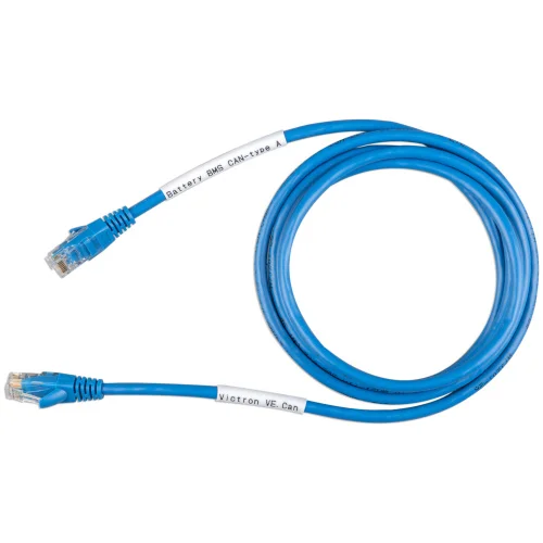
- Victron UTP RJ45 1,8m Victron UTP Cable - ASS030064950
- With Victron VEConfigure Software.
- To monitor the installation you will need: The Victron Cerbo GX MK2 Monitoring - BPP900451100 or the Display Victron Color Control GX - BPP010300300100R.
- If it is decided to install the Cerbo, a screen can be added at a later date: Monitoring Victron GX Touch 70 - BPP900455070.
- Access the Victron VRM Portal to remotely monitor and configure the installation.
- In terms of storage, the lithium battery 4.8kWh Pylontech US5000 48V is the perfect companion to the Multiplus II 48/5000.
- For measuring battery voltage and temperature: Victron VE.Bus Smart Dongle Adapter - ASS030537010.
- For implementing PowerControl and PowerAssist and optimising self-consumption with external current sensor: Victron current transformer for MultiPlus-II (1m) - CTR110000500.
- For remote monitoring and for configuring PowerControl and PowerAssist settings: Digital Panel Victron Multicontrol 200/200A - REC020005010.
- To monitor the battery: Battery Monitor BMV-712 Smart Victron - BAM030712000.
- With Bluetooth to use the VictronConnect App.
FAQs of the Victron MultiPlus II 48/5000
What is Victron MultiPlus
It is a device that combines an inverter and a charger in a single unit.
Victron Multiplus on/off switch
The Victron victron victron multiplus ii 48/5000 has the on/off switch on the bottom. 0 is off, I is on and II is charger only.
How to configure Victron Multiplus
See section "Configuring the Victron Multiplus".
How to program Victron Multiplus II 48/5000
See section "Installation and assembly of the Victron MultiPlus II 48/5000 VA Inverter - PMP482505010".
How to update the Victron Multiplus firmware
By using the VictronConnect App or through the Victron VRM Portal.
How to install Victron Multiplus
See section "Installation and assembly of the Victron MultiPlus II 48/5000 VA Inverter - PMP482505010".
What is the difference between Victron Multiplus and Multiplus II?
The Multiplus II combines the functionality of the Multiplus and Multigrid models.
Inverter Victron MultiPlus II 48/5000 VA 48V 70+50A manual and datasheet - PMP482505010
In case you need more information, here is the MultiPlus II 48/5000 datasheet and manual.
Technical Data Sheet Inverter Charger Victron Multiplus 48/5000
Additional information
| Weight | 30 kg |
|---|---|
| Dimensions | 56,5 × 32 × 14,9 cm |
Product reviews
1 review for Inversor Cargador 48V Victron MultiPlus II 48/5000 VA 48V 70+50A – PMP482505010
Add a review Cancel reply
You must be logged in to post a review.






David Albaladejo -
One of the best you can find in stand-alone inverters. It is very resistant to motor starting peaks. HIGHLY RECOMMENDED!