- Free shipping to mainland Spain for orders over 300€.
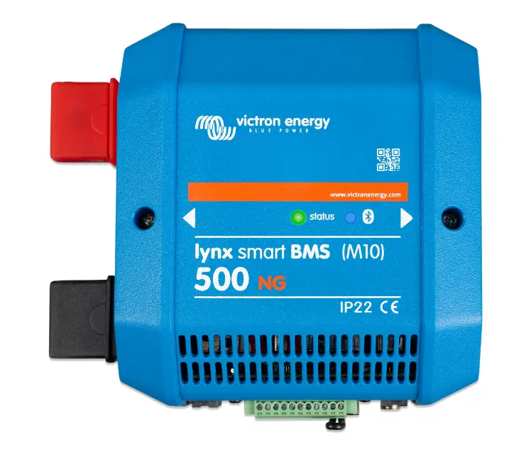
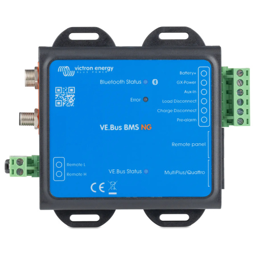
Lynx Smart BMS 500 NG (M10) Victron - LYN034160310
613,49€
TAXES INC.
- Specific BMS for the NG battery series.
- Battery voltage range: 9 - 60 VDC
- Maximum input voltage: 75 VDC
- Accepted system stresses: 12, 24 or 48 V
The product photograph is for illustrative purposes only and may not match the actual product.
Product available for sale

Finance your purchase with Cetelem
Reference:
LYN034160310
Categories: Accessories for solar batteries, Solar batteries, BMS for lithium batteries, Battery monitors
Details of the Lynx Smart BMS 500 NG (M10) Victron - LYN034160310
Lynx Smart BMS 500 NG (M10) Victron - LYN034160310
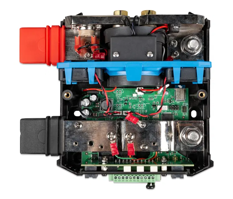
The Lynx Smart BMS 500 NG (M10) Victron - LYN034160310 is a battery management system (BMS) designed specifically for Victron's NG series of lithium batteries. These LiFePO4 batteries are available in 12.8V, 25.6V and 51.2V and in different capacities.
The maximum number of NG lithium batteries that can be connected to the NG BMS is 50 units. For a 12V system this means a maximum energy storage of 192 kWh and up to 384 kWh in 24V and 48V systems.
The maximum energy storage capacity can be multiplied by connecting several NG BMSs in parallel, which also ensures redundancy if one bank fails.
of batteries.
Among the various BMS available for the new Lithium NG batteries, the Lynx Smart BMS NG is the most comprehensive and feature-rich option and integrates easily with other M10 products in the Lynx distributor system.
Lynx Smart BMS 500 NG (M10) specifications
- Battery voltage range: 9 - 60 VDC
- Maximum input voltage: 75 VDC
- Accepted system stresses: 12, 24 or 48 V
- Reverse polarity protection: No
- Rated continuous current of the main safety contactor: 500 A continuous
- Peak current of the rated main safety contactor: 600 A for 5 minutes
- Power consumption in OFF mode: 0,3 mA for all system voltages
- Standby power consumption: Approximately 0.6 W (50 mA at 12 V)
- Power consumption in ON mode: Approximately 2.6 W (217 mA at 12 V) depending on the relay status
- Minimum load resistance for pre-loading:
- 10 Ω and above for 12 V systems
- 20 Ω and above for 24 V and 48 V systems
- Maximum rated current of the AUX output: 1.1 A continuous, protected by a resettable fuse
- ATC port (enable charging) Maximum rated current: 0.5 A at 60 VDC, protected with a resettable fuse
- ATD port (enable discharge) Maximum rated current: 0.5 A at 60 VDC, protected with a resettable fuse
- Single-pole double-touch alarm relay (SPDT) Maximum rated current: 2 A at 60 VDC
Features of the BMS 500 NG
Integrated contactor
- Acts as a secondary safety system to protect the battery in case of failure of the main controls (ATC, ATD and/or DVCC).
- Suitable as main switch of the remote controllable system.
Pre-charge circuit
- Prevents high inrush currents when capacitive loads such as inverters are connected.
- Eliminates the need for external preloading devices.
Closed-loop control DVCC and ATC/ATD contacts
- Compatible Victron inverter/chargers, Orion XS 12/12-50 A converter and solar charge controllers are automatically controlled by a connected GX device and DVCC.
- The ATC (enable charge)/ATD (enable discharge) contacts can be used to control other chargers and loads that have a remote on/off port.
Communication and interfaces
- It has Bluetooth to connect to the VictronConnect App.
- It also has a VE.Can port for connecting to GX devices with a standard RJ45 network cable and monitoring the system via the Victron VRM portal.
- Integration into marine networks via NMEA 2000 protocol (requires a male micro-C VE.Can to NMEA 2000 cable).
- The integrated battery monitor provides data such as state of charge, voltage, current, historical data and status information, among other things, in real time.
- Diagnostics at a glance with Instant Readout.
- Fuse status monitoring of up to four Lynx distributors connected via VictronConnect or GX devices.
- Reception of alarms in case of blown fuses.
Programmable relay
- It can be used as an alarm relay (together with the pre-alarm) or to control an alternator via its external regulator (ignition cable).
- An ATC alternator mode is available to safely disconnect the alternator before the battery is disconnected.
AUX terminal
- On-board auxiliary power supply (1.1 A at system voltage) to provide power to individual loads after the BMS has shut down.
- Automatic shutdown of the BMS and AUX connection if no charging voltage is detected within 5 minutes in the event of low voltage.
Lynx Smart BMS redundant parallel BMS
- The new parallel redundancy option of the Lynx Smart BMS and Lynx Smart BMS NG series allows for multiple Lynx BMSs in an installation. Each has its own battery bank and together they form a single redundant battery system. Up to five BMS can be connected in parallel.
NG 500A BMS Connections
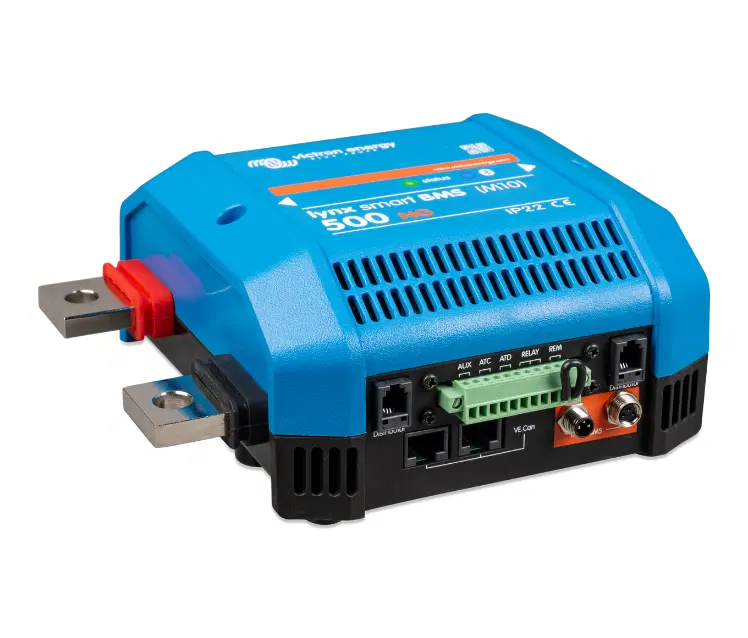
- Muddy: M10 (Torque: 33 Nm) - can be combined with all Lynx M10 products
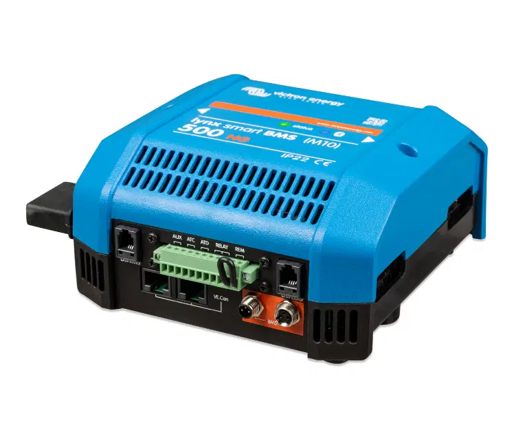
- VE.Can: RJ45
- I/O: Removable multi-connector with screw terminals
- Battery BTV cables: 3-pole circular male and female connector with M8 screw ring. Up to 50 batteries can be connected in one system
- Lynx distributor fuse monitoring (up to four modules): RJ10 (one cable is supplied with each Lynx distributor)
Working conditions
- Working temperature range: -40 °C to +60 °C
- Storage temperature: -40 °C to +60 °C
- Humidity (non-condensing): Max. 95 %
- Protection class: IP22
Overview of the Lynx Smart BMS 500 NG
- Housing material: ABS
- Housing dimensions: 190 x 180 x 80 mm
- Weight: 1.9 kg
- Busbar material: Tinned copper
- Busbar dimensions: 8 x 30 mm
- Standards:
- Security: EN-IEC 63000:2018
- EMC: EN-IEC 61000-6-3:2007/A1:2011/AC:2012
- QMS: NEN-EN-ISO 9001:2015
Installation of the BMS NG
System sizing
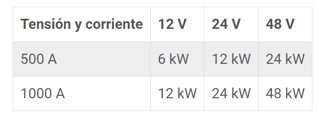
The BMS NG has a rated continuous current of 500 A and a rated peak current of 600 A with a duration of 5 minutes. It must be ensured that the rated current is not exceeded. If the peak current limit or the 5-minute interval is exceeded:
- An overcurrent alarm will be generated.
- ATC or ATD (allow charging or allow discharging) (depending on the current direction) is disabled after 30 seconds.
This table shows the power rating of a Lynx Smart BMS NG at different voltages:
Assembly
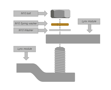
The materials required and the order is the same for both interconnecting Lynx modules and connecting the DC cables, which must have M10 terminals.
First of all, the end of the Lynx busbar or DC cable is fitted, followed by the washer, the spring washer and the screw nut. Tighten the nuts with a torque of 33 Nm.
The busbar ends of the Lynx are fitted with rubber busbar protectors, if nothing is to be connected to them, they should be left on.
Connecting the BMS cables
If multiple batteries are used (up to 50 batteries per BMS NG), first connect the BMS cables of the lithium battery and then connect the BMS cable of the first and last battery to the BMS connectors of the Lynx Smart BMS NG.
Connecting the multi-connector
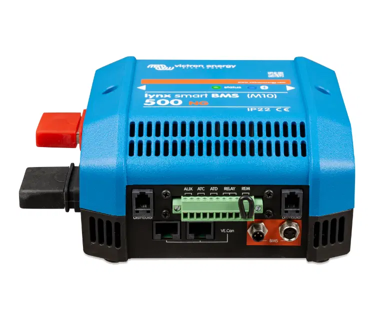
The Lynx Smart BMS NG multi-connector has 13 pins numbered from left to right, starting with pin 1 and ending with pin 13. Pins 12 and 13 are reserved for future functions.
- Pins 1 and 2 AUX:
- To supply voltage to other pins, such as ATC or ATD.
- Pins 3 and 4 ATC (Allow Load)
- To control system chargers that have a remote on/off connector.
- They can also be used to connect a BatteryProtect.
- Pins 5 and 6 ATD (Allow discharge):
- To control system loads that have a remote on/off connector.
- A common example is to provide +12 V connected from AUX + (equal to the system voltage) to pin 3 and pin 5. This provides an active high signal to the connected remote H-ports of the chargers and loads via pin 4 respectively pin 6. In case of low cell voltage, ATD opens the contact between pin 5 and pin 6. The load is then switched off to prevent further discharge. If the temperature is too low for charging, the ATC contact between pin 3 and pin 4 opens and switches off the chargers. Instead of using the system voltage at AUX +, the system negative at AUX - can be used to generate an active L-signal. The function is the same as described above, except that the low signal ensures that the loads and chargers are turned off. The active L signal can then be connected to the remote L terminals of a charger or load. Unlike the H signal, the system negative is also present if the contactor opens and the Lynx Smart BMS NG enters OFF mode.
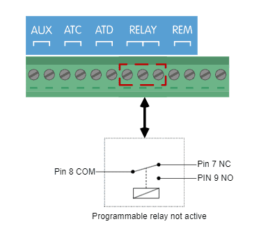
- Pins 7,8 and 9 RELAY:
- It is a single-pole touch relay with three contacts.
- Common (COM), normally open (NO), normally closed (NC).
- The relay makes contact between COM and NC when it is not active, while COM and NO make contact when the relay has been activated.
- An audible device (acoustic signal) or visible device (LED signal) or the signal line (usually the ignition cable) for the ATC signal of an external alternator regulator can be connected.
- Pins 10 and 11 REM:
- An on/off switch can be connected to remotely switch the Lynx Smart BMS NG on and off. The pre-installed metal ring must be removed.
- The H terminal (pin 10) is energised, usually the positive of the battery and the L terminal (pin 11) must be grounded, usually the negative of the NG lithium battery.
- The maximum voltage is 70V and the minimum voltage is -70V.
- Power level of pin 10 (H terminal) > 3V.
- Power level of pin 11 (L terminal) < 5V.
ATC and ATD contacts can also be used as remote switches, such as to control a Smart BatteryProtect to shut down loads in case of low cell voltage or a charger in case of low temperature.
Connecting the GX device
Connect the VE.Can port of the Lynx Smart BMS to the VE.Can port of the GX device with an RJ45 cable.
Example installation of Lynx Smart BMS NG
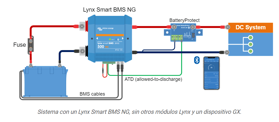
For when the system has only one lithium battery or a single series string of lithium batteries together with a single DC system.
Without a GX device, it is impossible to control inverter/chargers and DVCC-compatible MPPTs via DVCC, although it is not essential for the operation of the BMS NG.
Integration into the Lynx distributor system
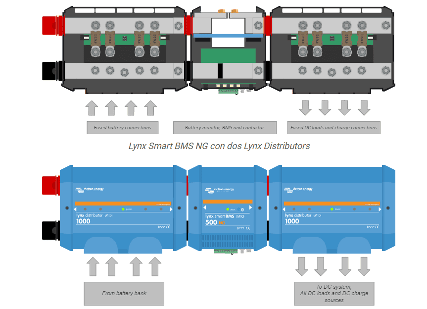
The NG battery should always be connected to the left side of the Lynx Smart BMS NG and all loads and chargers are connected to the right side.
The picture below shows a system with two Lynx Distributors and the BMS NG. Together they form a continuous busbar with fused battery connections, battery monitor, BMS system, connector and fused load connections.
Each Lynx module has two RJ10 connectors, one on the left and one on the right.
- The end of the RJ10 cable must be plugged into the RJ10 connector on the Lynx distributor, with the retaining clip on the RJ10 connector facing away from the RJ10 connector.
- The RJ10 cable is passed through the slot on the bottom of the Lynx distributor and the RJ10 cable is plugged into the RJ10 connector on the bottom of the Lynx Smart BMS NG.

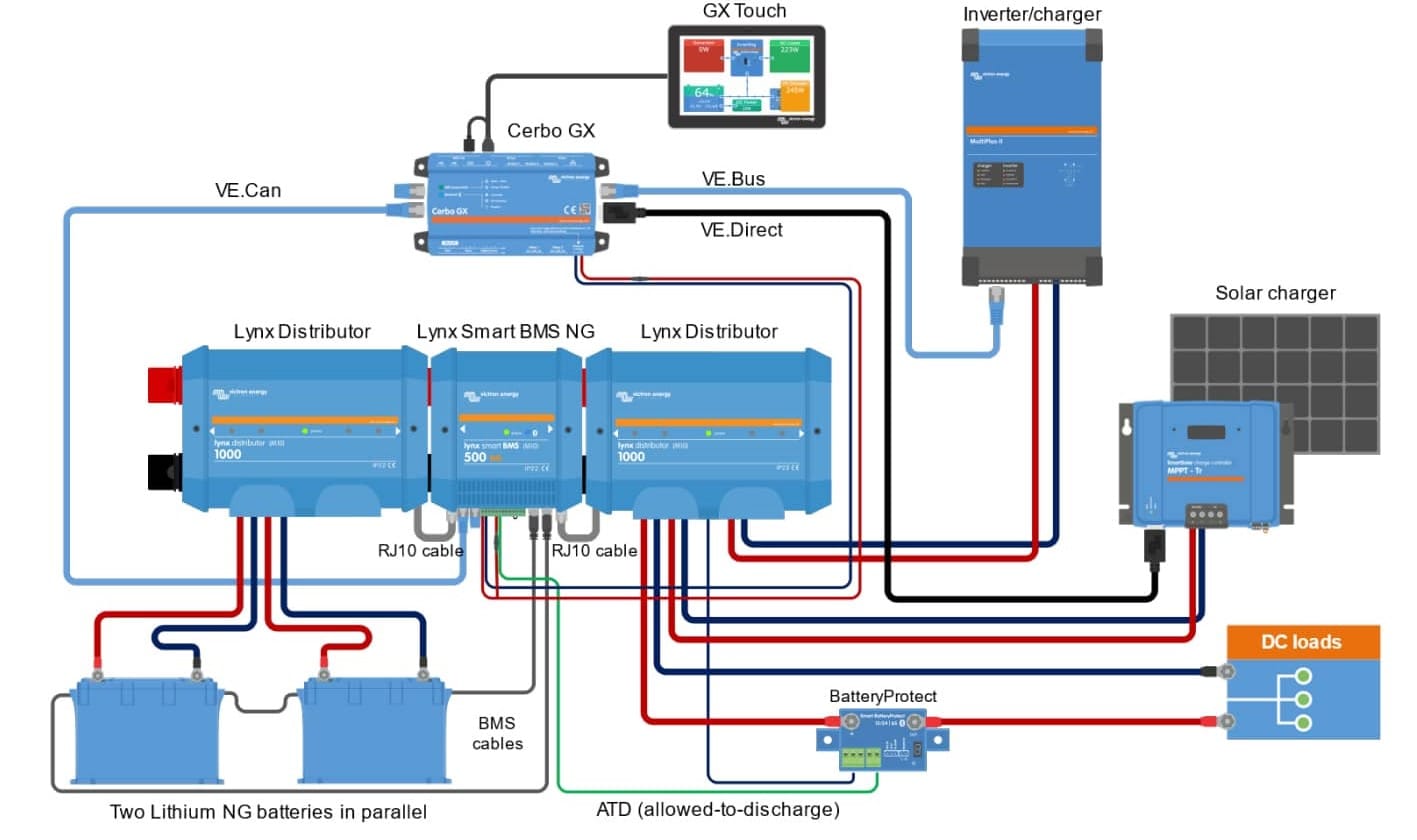
Example installation of BMS NG with Lynx Distributor and NG Batteries
This system consists of:
- 2 LiFePO4 NG batteries in parallel.
- A battery protector.
- Lynx Distributor M10.
- Lynx Smart BMS NG 500 A with BMS, contactor and battery monitor.
- Other Lynx Distributor M10
- Provides fused connections for inverter/chargers, loads and chargers.
- An inverter, an MPPT and solar panels.
- DC loads.
- A Cerbo GX MK2 and a GX Touch screen.
If you want to create a redundant battery bank, see section 6 of the NG 500A BMS manual (link at the end of the sheet).
List of materials required for installation
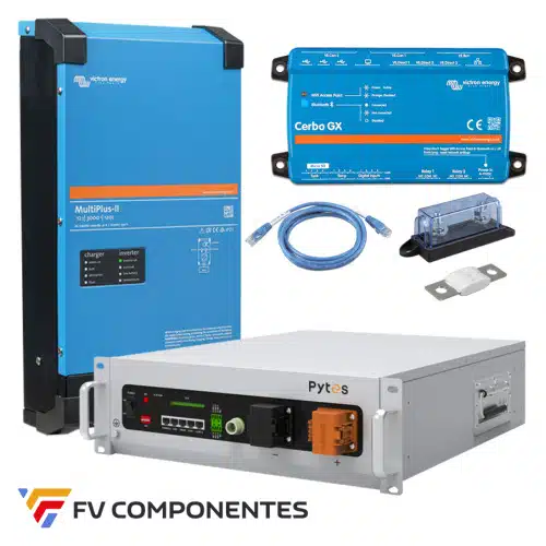
- If you want to monitor the system remotely, it is necessary to install a GX device, such as the Monitoring Victron Cerbo GX MK2 - BPP900451100.
- An RJ45 cable is required to connect it to the BMS: Victron UTP RJ45 RJ45 Cable 3m - ASS030064980.
- Victron VRM Portal.
- To monitor the BMS via Bluetooth connection, download the VictronConnect App.
- You may need extension cables to connect the lithium batteries to the BMS: Victron cable with 3-pole M8 male/female circular connector 5 m - ASS030560500
- And for integration into marine networks using the NMEA 2000 protocol, you need the Victron micro-C male Victron VE.Can to NMEA 2000 cable - ASS030520200
Commissioning of the BMS NG
First ignition
The Lynx Smart BMS NG will turn on when an NG lithium battery is connected, the metal ring is placed on pins 10 and 11 of the multi-connector or the remote on/off switch is turned on.
The Lynx Smart BMS NG automatically determines and sets the following settings:
- System voltage, 12, 24 or 48 V, by measuring the battery voltage.
- Number of batteries arranged in parallel, series and parallel/series combination.
- Number of cells per battery.
- Pre-alarm mode enabled by default. In the event of a pre-alarm, a visual or audible device linked to the programmable relay is activated.
Other adjustments:
- Relay mode:
- Alarm relay mode:
- Intermittent operation, relay switches on and off every 0.8 seconds.
- Continuous operation.
- Alternator ATC (Allow Load) mode, the relay is only activated when the contactor is closed.
- Before the contactor opens, the ATC Alternator opens first and two seconds later the contactor opens. These two seconds ensure that the alternator regulator is switched off before the battery is disconnected from the system.
- DVCC settings:
- Pre-alarm discharge current limit:
- Default: No.
- If "Yes" is activated: the discharge current limit is set to 0 A in case of pre-alarm, while the ATC contact (enable load) remains closed.
- Absorption time: 2 hours
- State-of-charge threshold: 70%
- Repeated uptake interval: 30 days
- The number of days after which a new full charge cycle is initiated if the battery state of charge does not fall below the state of charge threshold.
- Pre-alarm discharge current limit:
- Battery monitor settings:
- Almost all settings of the Lynx Smart BMS NG battery monitor are fixed and cannot be adapted, as it is specially designed for NG lithium batteries.
- More information can be found in section 4.3 of the manual (link below).
- Alarm relay mode:
Update
Updating the Lynx Smart BMS NG firmware can be done in two ways:
- Via the VictronConnect application.
- Via the VRM portal: The remote firmware update option (requires a GX device connected to the Internet).
Start-up sequence
In section 5 of the manual you will find the necessary checklist for commissioning.
Lynx Smart BMS 500 NG Victron features
Functions performed by the BMS NG:
The BMS NG can control loads and chargers in two ways:
- Sending an electrical or digital on/off signal to the charger or load.
- By physically connecting or disconnecting a load or charging source from the battery. Directly or by using a BatteryProtect or a Cyrix Li-ion relay.
The Lynx Smart BMS NG is used in systems containing DC and AC loads via inverters or inverter/chargers, for example in boats or caravans.
- In case of low cell voltage, the BMS NG will send a "load disconnect" signal to switch off the load(s).
- Before shutting down a load, it will send a pre-alarm signal indicating impending low cell voltage.
- In case of high cell voltage or low or high battery temperature, the BMS NG will send a "load disconnect" signal to switch off the charger(s).
- If the batteries are further discharged (or overcharged), the contactor will open, effectively disconnecting the DC system to protect the batteries.
Lynx Smart BMS 500 NG (M10) Victron Manual and Datasheet - LYN034160310
In case you need more information, here is the manual and the technical data sheet:
Weight and dimensions
| Weight | 2 kg |
|---|---|
| Dimensions | 19 × 18 × 8 cm |
User feedback
Be the first to review "Lynx Smart BMS 500 NG (M10) Victron - LYN034160310" Cancel reply
You must be logged in to post a review.





Reviews
There are no reviews yet.