- Free shipping to mainland Spain for orders over 300€.
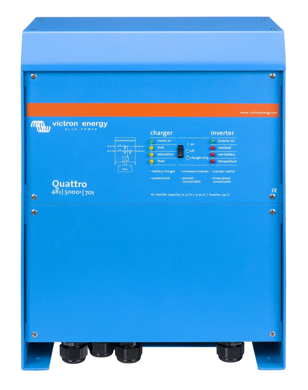
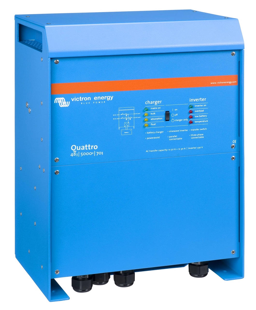
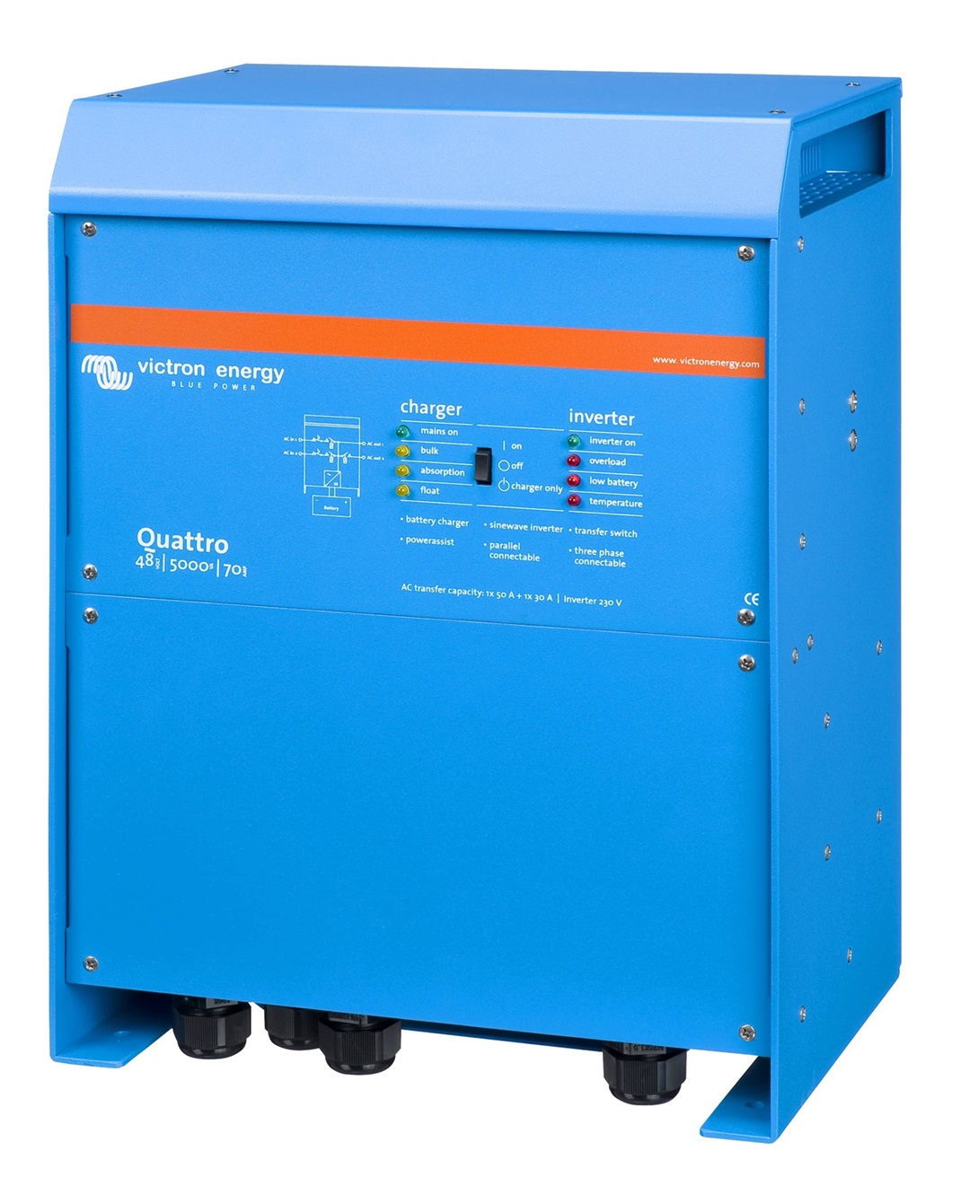
Inverter 48V Victron Quattro 48V 5000VA 70-100/100 120V UL - QUA482501102
1.633,12€
TAXES INC.
- Inverter Charger
- Output voltage: 120V
- Inverter Peak Power: 10000W
- Inverter Operating Voltage: 48V
- Continuous power output: 5000VA
- Weight of the Investor: 30Kg
- Inverter Dimensions: 444 x 328 x 240 mm
110V-120V equipment on request, special sales conditions on request.
Producto disponible para la venta

Finance your purchase with Cetelem
Reference:
QUA482501102
Categories: 110V - 120V equipment, Inverter Chargers 48V to 110V, Inverters 110V chargers
Product information
Victron Quattro 48V Inverter Specifications 48V Victron Quattro 48V 5000VA
Investor
- Input voltage range (VDC): 19 - 33 V
- Output voltage range: 120 VAC ± 2 %
- Frequency: 60 Hz ± 0,1 %
- Power cont. output at 25°C / 77ºF: 5000 VA
- Power cont. output at 25°C / 77ºF:4000 W
- Power cont. output at 40°C / 104ºF: 3700 W
- Power cont. output at 65°C / 150ºF: 3000 W
- Peak power: 10000 W
- Maximum efficiency: 95%
- No-load consumption: 35W
- No-load consumption in economy mode: 30 W
- Idle consumption in search mode: 15 W
Charger
- Absorption' charging voltage (VDC): 57,6V
- Float" charging voltage (VDC): 55,2V
- Storage" mode (VCC): 52,8V
- House battery charging current (A): 70 A
- Battery temperature sensor: Yes
Advanced features of the Victron Quattro 48V Inverter 48V 5000VA 70-100/100 120V UL - QUA482501102
- On-site monitoring and control: Several devices can be used to perform this function: Battery Monitor, Multi Control panel, Ve.Net Blue Power panel, Color Control GX and other smartphone or tablet devices (Bluetooth Smart), laptop or computer (USB or RS232).
- Remote monitoring and control: By using Color Control GX and other GX devices. Data can be stored and displayed on the web VRM (Victron Remote Management).
- Remote configuration: Data can be accessed and system settings can be changed with a Color Control GX and other GX devices if connected to Ethernet.
- Three-phase and split-phase operation capability: Two units can be configured for split-phase output and three units for three-phase output. But also up to 4 groups of three units can be connected in parallel to achieve 96kW / 120kVA inverter power and more than 1600 A load capacity.
- Two AC inputs with integrated transfer switch: The Quattro can be connected to two independent AC power sources; such as the pontoon grid or a generator, or two generators. The Quattro Victron will automatically connect to the active power source.
- Two AC outputsThe main output has a "no-break" function. The victron quattro 48/5000 takes over the supply to the connected loads in the event of a blackout or disconnection of the mains or generator. This happens so quickly (less than 20 milliseconds) that the operation of computers and other electronic equipment is not affected. The second output is only active when AC power is supplied to one of the inputs of the Quattro. Devices that should not discharge the battery, such as a water heater, for example, can be connected to this output.
- PowerControl: A current limit can be set for each of the AC inputs. The Quattro will then take the other AC loads into account and use the excess current for battery charging, thus avoiding overloading the generator or the pontoon network.
- PowerAssist: This function takes the PowerControl principle to another dimension, allowing the victron quattro inverter to supplement the capacity of the alternative source. When a power peak is required for a short period of time, as is often the case, the Quattro inverter will immediately compensate for the possible lack of power from the pontoon current or generator with power from the battery. When the load is reduced, the excess power is used to recharge the battery.
- Solar energy: AC power available even during a blackout. The victron energy quattro can be used in PV systems, whether grid-connected or off-grid, and in other alternative electrical systems.
Quattro Inverter Battery Charger Features
- 4-stage variable loading: initial - absorption - flotation - storage
- The microprocessor-activated variable battery management system allows adjustment to different battery types. This variable function automatically adapts the charging process to the battery usage.
- The right amount of load: variable absorption time
- If the battery is slightly discharged, the absorption is reduced to avoid overcharging and excessive gassing. After a deep discharge, the absorption time is automatically extended to fully charge the battery.
- Preventing damage due to over-gassing: BatterySafe mode
- If a combination of high charging current and high absorption voltage (to charge the battery quickly) has been chosen, damage due to over-gassing will be prevented by automatically limiting the rate of voltage increase once the gassing voltage has been reached.
- Storage mode: Less ageing and need for maintenance when the battery is not in use:
- The storage mode is activated if the battery has not been discharged for 24 hours. In storage mode, the float voltage is reduced to 2.2 V/cell (13.2 V for 12 V batteries) to reduce gassing and corrosion of the positive plates. Once a week, the voltage is raised to absorption level to "equalise" the battery. This function prevents electrolyte stratification and sulphation, the main causes of battery failure.
- Two DC outputs for charging two batteries
- The main DC terminal can supply the full output current. The second output, intended for charging a starter battery, is limited to 4 A and has a slightly lower output voltage.
- Increased battery lifetime: temperature compensation
- The temperature sensor serves to reduce the charging voltage if the battery temperature rises. This is crucial for maintenance-free batteries that would otherwise dry out due to overcharging.
- Battery voltage sensor: the right charging voltage
- Voltage loss due to cable resistance can be compensated for by using the voltage probe to measure the voltage directly at the DC bus or at the battery terminals.
Victron Quattro 48V 5000VA 120V UL Installation
The first thing to bear in mind:
- The victron Quattro should be installed in a dry, well-ventilated area as close to the batteries as possible.
- A free space of at least 10 cm should be left around for ventilation.
- Can be mounted on the wall. Never place directly on batteries.
- It must be installed away from heat sources and in a place at a suitable temperature.
- An excessively high ambient temperature has the following consequences:
- Shorter life cycle
- Underload current
- Lower peak power or inverter shutdown
- An excessively high ambient temperature has the following consequences:
- The inside of the device must remain accessible after installation.
- The distance between the victron quattro and the battery should be as small as possible to minimise voltage loss in the cables.
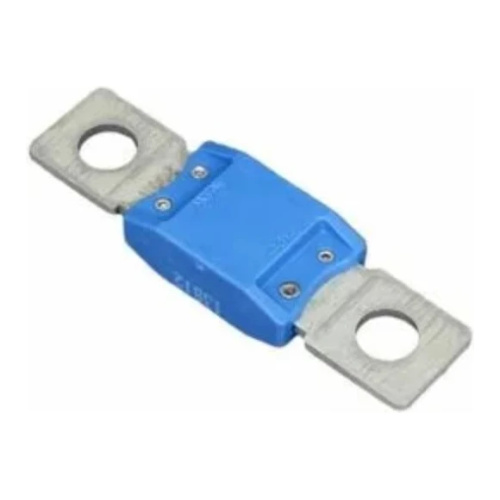
- The Quattro inverter does not have internal DC fuses. The DC fuse must be installed outside the Quattro.
- Do not expose the charger to rain or snow.
- Only VRLA or rechargeable lithium-ion batteries may be charged. Other types of batteries may explode, causing damage and personal injury.
- Connect and disconnect the DC output connections only after the switches on the marine units have been turned off and the AC power cord has been removed from the electrical outlet or the AC disconnect has been opened.
System configuration
- In the case of a stand-alone application, if the configuration needs to be changed, this can be done quickly by means of a DIP-switch setting procedure.
- Parallel or three-phase applications can be configured with the VE.Bus Quick Configure and VE.Bus System Configurator software.
- Off-grid, grid-interactive and self-consumption applications involving grid-connected inverters and/or MPPT solar chargers can be configured with Wizards (application-specific software).
Connecting the battery cables
- Recommended battery capacity: 200-800Ah
- Recommended DC fuse: 200 A
- Recommended cross-section (mm2) for + and - terminals:
- 0 - 5 m: 1x 70 mm² (one positive and one negative wire)
- 5 -10 m: 2x 70 mm² (two positive and two negative wires)
Procedure
- An insulated torque spanner must be used to avoid short-circuiting the battery. Maximum torque: 14 Nm
- Remove the DC fuse.
- Loosen the four lower front panel screws on the front of the unit and remove the lower panel.
- Connect the battery cables: + (red) to the right terminal and - (black) to the left terminal.
- Tighten the connections after mounting the fasteners.
- Tighten the nuts securely so that the contact resistance is minimal.
- Replace the DC fuse after the entire installation procedure.
Victron quattro connections
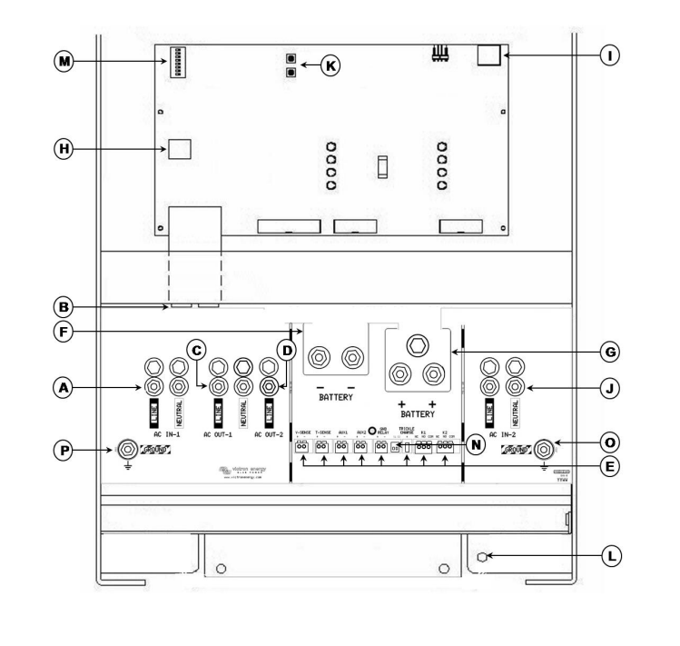
The following picture shows the connections of the quattro victron 48V 5000VA:
- A: AC input M6 (generator input) AC-in-1. Left to right: L (phase), N (neutral).
- B: 2 RJ45 connectors for remote panel and/or parallel or three-phase operation.
- C: AC output M6 AC-out-1 Left to right: L (phase), N (neutral).
- D: AC output M6 AC-out-2 Left to right: N (neutral), L (phase).
- E: Terminals: (left to right)
- Voltage sensor
- Temperature sensor
- Aux 1 input
- Aux 2 input
- Relay GND (ground)
- Starter battery positive + (negative of the starter battery must be connected to the negative of the service battery)
- Contacts of programmable relay K1.
- Contacts of programmable relay K2
- L: Connection of the negative of the battery by means of double M8.
- G: Double M8 battery positive connection.
- H: Connector for remote switch:
- Short and medium left terminal to "switch on".
- Short and middle right terminal to switch to "charger only".
- I: Alarm contact: Left to right: NC, NO, COM.
- J: AC input M6 (pontoon/network supply) AC-in-2. Left to right: L (phase), N (neutral).
- K: Push buttons for configuration mode
- L: Primary earth connection M8 (PE).
- M: DIP switches for configuration mode.
- N: Potentiometers, factory setting SW1 = off position, SW2 = off position.
- SW1: Off = internal GND relay selected, On = external GND relay selected (to connect ext GND relay: see E).
- SW2: No function. For use in future functions.
- O: Common ground connection M6 (ground) for AC IN-2.
- P: M6 (ground) connection for AC-IN-1, AC-OUT-1.
Three-phase connection
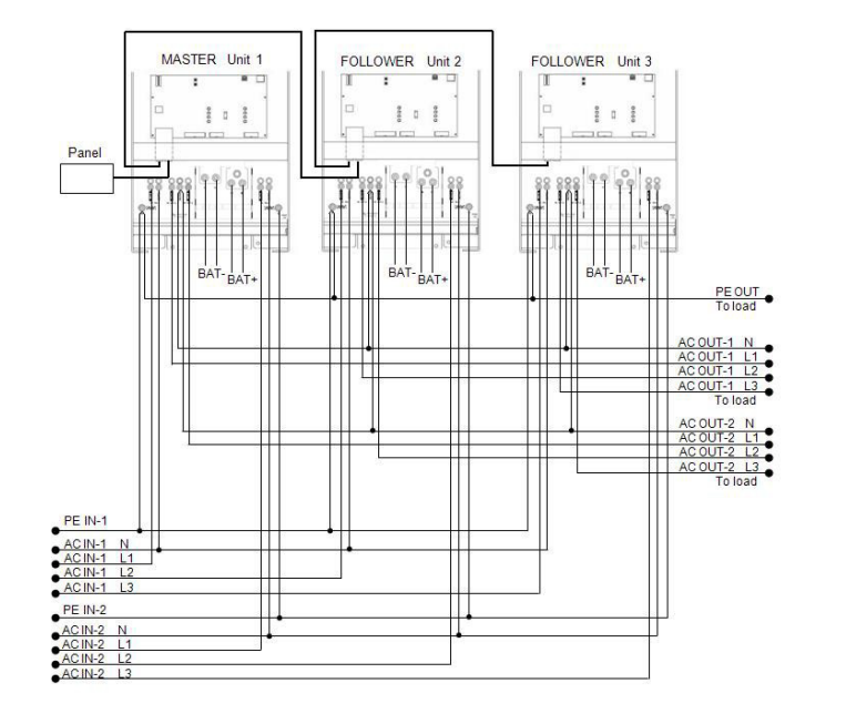
The victron quattro inverter can also be used in a three-phase i Greek (Y) configuration. For this purpose, a connection is made between devices via standard RJ45 UTP cables. The system will have to be configured afterwards. The Quattro is not suitable for a three-phase delta (Δ) configuration.
This is the diagram to follow for a three-phase connection of the victron quattro 48V 5000VA 120V UL:
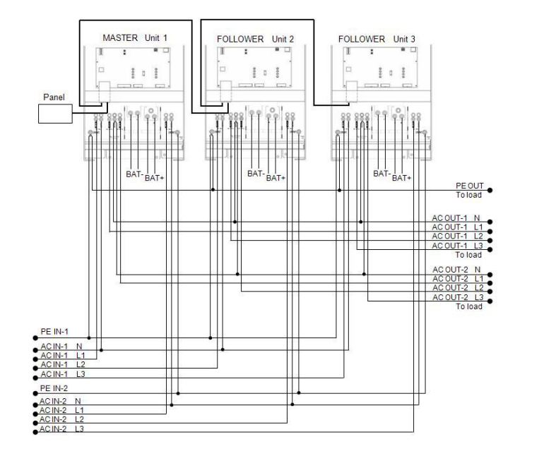
Parallel connection
Up to 6 identical victron quattro inverters can be connected in parallel. A connection between the devices is established via standard RJ45 UTP cables.
The following conditions must be met:
- A maximum of 6 units connected in parallel.
- Only identical devices with the same power rating should be connected in parallel.
- The battery capacity must be sufficient.
- The DC connection cables to the devices must all have the same length and cross-section.
- If a negative and a positive DC distribution point is used, the cross-section of the connection between the batteries and the DC distribution point must be at least equal to the sum of the required cross-sections of the connections between the distribution point and the Quattro units.
- Place the Quattro units side by side, but leave at least 10 cm around each inverter for ventilation.
- UTP cables must be connected directly from one unit to the other (and to the remote panel). No junction/distribution boxes are allowed.
- The battery temperature sensor only has to be connected to one unit in the system. If the temperature of several batteries is to be measured, the sensors of other Quattro units in the system can also be connected (maximum one sensor per Quattro).
- The voltage sensor must be connected to the Quattro master inverter.
- Only one remote control device (panel or switch) can be connected to the system.
This diagram shows how to connect the victron energy quattro in parallel.
48V Inverter Victron Quattro 48V 5000VA 70-100/100 120V UL Manual and Datasheet - QUA482501102
Here you can find the manual and the technical data sheet of this Victron quattro:
Technical data sheet 48V Inverter Victron Quattro 48V 5000VA 120V
Additional information
| Weight | 30 kg |
|---|---|
| Dimensions | 44,4 × 32,8 × 245 cm |
Product reviews
Be the first to review “Inversor 48V Victron Quattro 48V 5000VA 70-100/100 120V UL – QUA482501102” Cancel reply
You must be logged in to post a review.






Reviews
There are no reviews yet.